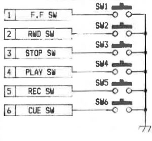
The switching circuit for the auto-locator is a very simple circuit. The MTR-12 sends out a voltage on a separate pin for each switch and, if any of these are shorted to GND, that switch is considered to be pressed.
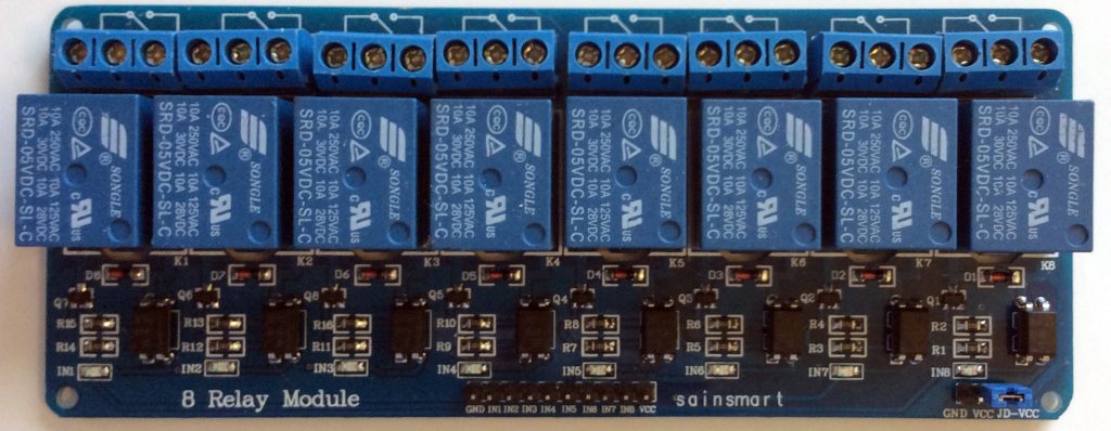
The Arduino can’t really do this, so I purchased an 8 relay module from here.

This module is designed to work with the Arduino (or any other microcontroller) and… it was only $10.49, which appealled to my cheapness immensely. 🙂
The relays work like this: Each relay has three pins. If the relay is off, pins 1 and 2 are connected together, if it is on, pins 2 and 3 are connected together.
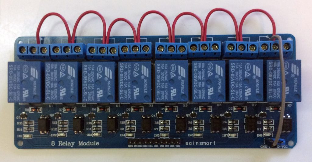
My plan is that I am going to connect all of the #2 pins together, and then connect them to GND. There is (happily) a spare GND pin on the relay module that I can use. It is meant for the little configuration jumper in the bottom right hand corner of the board, but it will serve my purposes well, and appears to be unused in the default configuration. Documentation on this module is pretty thin, and I can’t get a clear idea as to what the configuration jumper is for. I think it must change the relays from being on when the control line is LOW to being on when it is HIGH, but this is just a guess.

With the #2 pins all connected to ground, I will then connect the switch outputs from the MTR-12 to the #3 pins of the relays. It will be connected like this:
- Record Switch (Pin 1) -> Relay 1 (Pin 3)
- Play Switch (Pin 2) -> Relay 2 (Pin 3)
- Stop Switch (Pin 3) -> Relay 3 (Pin 3)
- Rewind Switch (Pin 4) -> Relay 4 (Pin 3)
- Fast Forward Switch (Pin 5) -> Relay 5 (Pin 3)
- Cue Switch (Pin 6) -> Relay 6 (Pin 3)
- Search Zero Switch (Pin 22) -> Relay 7 (Pin 3)
The first six were all of the switches in the CB-109 auto-locator. There was, however, another remote that was available for the MTR-12, the CB-111, and it used the same port. It was a very simple remote control, with no bells and whistles, but it did have a Search Zero switch that it needed an output for. I have decided to wire that up for this test, even though the CB-109 had that functionality moved into the keypad section, and didn’t use the searchZ switch output. More on that later. I have an extra couple of relays on this module anyway, so I may as well use this opportunity to see if the SearchZ Lamp comes on when I trigger it.
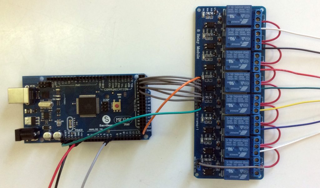
The connections between the Arduino and the Relay module as are follows:
- GND -> GND
- 5V -> Vcc (Power supply)
- D22 -> In 1 (Controls relay 1. LOW=On, HIGH=Off)
- D23 -> In 2 (Controls relay 2)
- D24 -> In 3 (Controls relay 3)
- D25 -> In 4 (Controls relay 4)
- D26 -> In 5 (Controls relay 5)
- D27 -> In 6 (Controls relay 6)
- D28 -> In 7 (Controls relay 7)
When I want a switch to be activated, all I will have to do is change the state of that digital output to LOW. To deactivate it, I simply change the state to HIGH. The switches will be:
- D22 Record
- D23 Play
- D24 Stop
- D25 Rwd
- D26 F.F
- D27 Cue
- D28 SearchZ
The whole thing wired together looks like this. I have removed the previous lamp wiring (except for the searchZ lamp) for clarity.

Tomorrow, I will hook it up to the MTR-12, write the code for the Arduino, and then do some testing.